LED Grow Light Beam Angle and Lenses: How Optics Decide Coverage
Two fixtures with the same PPF can leave one bench evenly lit and the other striped with bright bands and dark gaps. The difference is rarely the diodes. It is the geometry between the optic, the mounting height and the next fixture along the rail.
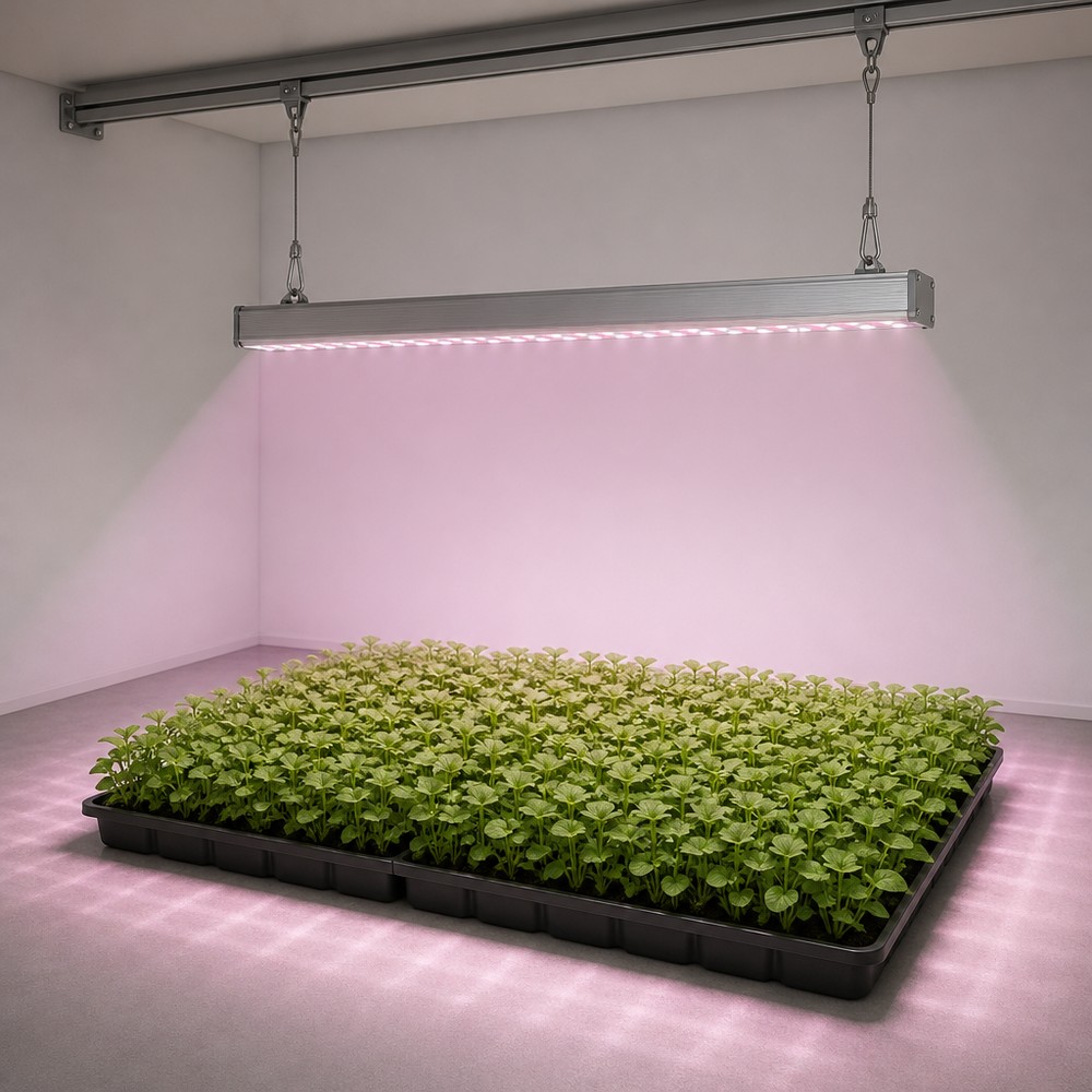
Three numbers set the coverage
Coverage under a grow light is decided by three quantities that are usually published separately, and therefore rarely evaluated together:
- Beam angle, which describes how the optic spreads light away from the fixture axis.
- Mounting height, the distance from the emitting surface to the canopy.
- Fixture spacing, the centre-to-centre distance along and across the bench.
Change any one of them and the PPFD map changes. This is why a supplier's claim of "covers 1.2 by 1.2 metres" is incomplete without the height and the spacing at which it was measured, and why two growers can install the same fixture and report opposite results.
What a beam angle figure actually means
Beam angle is normally quoted as the full angle between the two directions where intensity has fallen to half of its peak value, a convention inherited from general lighting. It is a description of the half-power width, not a hard boundary. Light continues beyond that angle, and in most horticultural fixtures a meaningful fraction of output sits outside the nominal cone.
Two consequences follow. First, a "90 degree" fixture still puts light on the floor 60 degrees off axis, so adjacent aisles and walls receive photons whether or not the layout intended it. Second, the beam angle alone cannot tell you the shape of the distribution inside the cone. A lens that produces a flat-topped pattern and one that produces a sharp centre peak can share the same half-power angle and behave completely differently over a canopy.
For that reason the useful specification is not the angle by itself but the angle together with a PPFD grid measured at a stated height. The grid shows the shape; the angle only shows the width.
Why a narrow beam is not automatically better
Narrow optics concentrate photons into a smaller footprint. That raises peak PPFD and reduces spill, which is attractive when the mounting point is high, the canopy is narrow, or the walls are far away. The cost is a steeper gradient: a 40 degree beam at 60 cm covers roughly 0.44 m across, and the intensity at the footprint edge is far below the centre value.
Wide optics flatten the pattern and let neighbouring fixtures overlap earlier, which usually improves uniformity across a bench. But the same photons are spread thinner, so average PPFD drops unless the fixture count rises. Neither choice is correct in isolation; the question is which one produces an acceptable minimum PPFD at the weakest point of the canopy for a given installed wattage.
Lenses and reflectors: what secondary optics do
An LED package already has a primary optic, usually a silicone dome that protects the die and shapes the raw emission into something close to a Lambertian pattern. Secondary optics sit in front of that dome and reshape the beam. The common options are total-internal-reflection lenses in PMMA or silicone, simple cover lenses that only protect and diffuse, and reflectors that redirect sideways emission downward.
Every one of them costs light. A lens introduces surface reflections and absorption, and a reflector loses photons that miss the reflective surface or are absorbed on each bounce. Manufacturers who quote a bare-diode efficiency and a finished-fixture efficiency separately are telling you how much the optic costs; when only one figure is given, the loss is hidden inside it.
Secondary optics also change how dirt behaves. A flat cover lens is easy to wipe and protects the diodes, but dust on its outer surface scatters light before it leaves the fixture, which is why dirty lenses lower output and soften the beam pattern at the same time. Exposed reflectors collect dust on the working surface and lose efficiency faster in a greenhouse with high humidity and foliage debris.
Optics compared
| Arrangement | Beam control | Optical loss | Best suited to | Main drawback |
|---|---|---|---|---|
| Bare diode, no secondary optic | Wide, roughly Lambertian | Lowest | Low rooms, dense multi-tier benches with close spacing | Large share of output leaves the canopy; edges of a room get lit |
| Flat protective cover lens | Little shaping; slight diffusion | Low | Wet or dusty rooms where diode protection matters | Does not fix distribution; surface fouling cuts output |
| TIR lens, narrow to medium | Strong, defined cone | Moderate | High bays, narrow benches, aisle containment | Hot spot under the fixture if spacing is too wide |
| Reflector | Moderate, redirects side emission | Moderate to higher | Retrofit housings and linear bars | Dust on the reflective surface; losses rise with bounce count |
| Asymmetric or batwing optic | Shaped to flatten the distribution | Moderate | Long benches where centre-to-edge uniformity is the priority | Needs correct orientation; wrong rotation throws light into the aisle |
Calculating footprint and overlap
For a circular beam, the illuminated diameter at a given height is a straightforward trigonometric result: D = 2 × h × tan(θ/2), where h is the mounting height and θ is the full beam angle. The table below applies it to four common angles. Treat the results as the half-power footprint, not the outer limit of usable light.
| Beam angle | 0.3 m | 0.6 m | 0.9 m | 1.5 m |
|---|---|---|---|---|
| 40° | 0.22 | 0.44 | 0.66 | 1.09 |
| 60° | 0.35 | 0.69 | 1.04 | 1.73 |
| 90° | 0.60 | 1.20 | 1.80 | 3.00 |
| 120° | 1.04 | 2.08 | 3.12 | 5.20 |
Overlap is then a spacing decision. If fixtures are placed at a centre-to-centre distance equal to their footprint diameter, the beams just touch and the midpoint between them sits in the weakest zone. Reducing spacing below the footprint diameter pushes overlap up and lifts the minimum PPFD, at the cost of more fixtures per square metre. This is the trade that a PPFD grid resolves in one pass, and that a beam angle specification cannot resolve on its own.
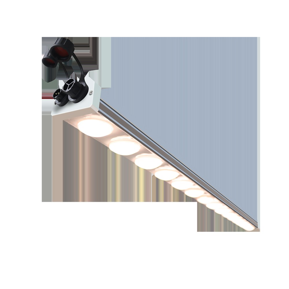
Linear bars behave differently from round beams: the cross-section follows the same geometry, but along the length of the bar the distribution is roughly constant, so spacing matters mostly across the bar rather than along it. That is why bar fixtures are usually mounted in rows with the spacing set by bench width.
Uniformity: how to measure and how to read a claim
Uniformity is normally expressed as a ratio of PPFD values across a grid, either minimum to maximum or minimum to average. The Illuminating Engineering Society's horticultural lighting material notes that both a U1 and a U2 metric have been proposed for horticultural design, which is precisely why a bare percentage in a brochure is ambiguous: the same layout can look excellent under one definition and mediocre under the other.
Two independent findings are worth keeping in mind when reading supplier claims. A review of LED illumination for protected cropping stresses that the fixture layout has to be designed deliberately if uniform distribution is to be achieved, rather than assumed from the diode choice. A study comparing three spatial configurations of commercial horticultural LEDs found measurable differences in irradiance uniformity between the three layouts. In other words, the same luminaire can be even or uneven depending on where it is placed.
Practically, ask for three things: the grid spacing used, the height and centre-to-centre distance at which it was measured, and which uniformity definition is quoted. Without those, the number cannot be reproduced.
A practical layout procedure
- Fix the canopy, not the room. Measure the actual usable growing area; aisles and walkways do not need photons.
- Choose the mounting height from the crop and the structure. Clearance for workers, irrigation and canopy growth usually decides this before photometry does.
- Pick the beam angle that keeps the footprint inside the bench. Use the table above as a first pass, then confirm the distribution shape with the supplier's grid.
- Set spacing so that footprints overlap, then check the minimum. The design question is the weakest point on the canopy, not the brightest.
- Verify after installation with a meter on a grid. Fixtures drift in aim during installation, and a bar rotated a few degrees can throw a noticeable share of its output into the aisle.
Where each approach fits
Low multi-tier benches with 30 to 50 cm clearance are usually best served by wide-distribution bars or bare boards, because overlap comes cheaply at that height and a narrow optic would simply create a hot strip. Single-layer benches at 1.5 to 3 m, and greenhouse bays with wide trusses, generally need a narrower beam or a shaped asymmetric optic so that photons land on the crop rather than on the floor between rows.
Where the crop is grown in gutters or narrow troughs, an asymmetric optic oriented along the row can lift the light that would otherwise fall into the aisle. Where the room is white-walled and reflective, part of that spill returns to the canopy anyway, which is a legitimate reason to accept a wider optic and fewer fixtures.
Frequently asked questions
Does a wider beam angle always give better uniformity?
No. A wider beam spreads the same photons over a larger area, which lowers average PPFD and pushes more light past the canopy edge. Uniformity depends on how neighbouring fixtures overlap, not on the beam angle alone. A narrow fixture on tight spacing can be more even than a wide fixture spaced too far apart.
Can I raise the fixture instead of changing the optic?
Raising a fixture widens the footprint but reduces PPFD, and the loss grows faster than the area once you are far enough away for the inverse-square approximation to hold. In a low room, raising the light may also put the beam outside the walls or into the aisle, which wastes photons.
Are lenses worth the optical loss?
Lenses and reflectors absorb or scatter part of the output, but they can redirect light that would otherwise leave the canopy, tighten spacing and reduce spill into aisles. Judge the combination on measured luminaire efficacy and a PPFD grid, not on the optic alone.
What beam angle suits a high greenhouse bay?
There is no single answer, because mounting height, truss spacing and crop canopy width all change the result. Higher mounting points generally need narrower beams to keep photons on the crop, while low multi-tier benches need wide, overlapping beams. Confirm with a PPFD grid at the real mounting height.
About the publisher
XineLam is the lighting brand of Zhongshan City Ruixian Electronics Factory, a manufacturer with 17 years of experience in LED lighting and 300+ patents in China and internationally. The company produces linear horticultural bars, quantum boards and architectural luminaires, and supplies optical and photometric data so that layouts can be checked against a canopy rather than a room.
Optic choice follows the installation. Multi-tier benches with limited headroom usually favour wide-distribution bars with tight spacing; single-layer benches and greenhouse bays with high mounting points usually favour lenses that concentrate output on the crop. In both cases the layout should be confirmed with a PPFD grid at the intended height before the fixture count is fixed.
References
- Illuminating Engineering Society. Lighting Uniformity in Horticulture. (Discussion of U1 and U2 uniformity metrics proposed for horticultural design.)
- Review of LED illumination for protected cropping, via PubMed Central: LED Illumination for High-Quality High-Yield Crop Growth in Protected Cropping Systems. (Design of the LED setup is required to ensure uniform light distribution.)
- Applied Sciences (MDPI): Impact of LED Light Spatial Distribution on Photosynthetic Performance. (Comparison of three spatial LED configurations on irradiance uniformity.)