How Does LED Dimming Work? 0-10V, PWM and Triac Control Compared
An LED grow light is not dimmed the way an incandescent lamp was. There is no filament to starve of voltage. The driver holds the LED string at a regulated current, and dimming means telling that driver to deliver less current. Almost every dimming problem growers report — buzz at the bottom of the range, a fixture that jumps from off to 20 percent, a controller that works on one bar and not the next — comes back to this single fact: the dimmer is not controlling the LEDs, it is negotiating with the driver.

Why a grow light gets dimmed at all
Dimming in a controlled environment is a light-delivery decision before it is an energy decision. A canopy that receives the right photon flux at week six is over-lit at week one, and a fixture that cannot be turned down has to be hung higher or switched on and off in blocks. Dimming lets the same hardware deliver a lower photosynthetic photon flux density (PPFD) during propagation, and then follow the crop as it fills the bench.
The energy saving is real but not perfectly proportional. Input power falls broadly with light output, but driver efficiency is usually at its lowest at the very bottom of the range, so a fixture held at 10 percent spends a larger share of its input power on the driver than the same fixture at full output. In most installations the practical consequence is simple: dimming is efficient in the middle of the range, and switching off is still better than dimming to near zero.
Where dimming physically happens
There are only three places the control can act, and every product on the market is a variation on one of them:
- On the AC side, by chopping the mains waveform before it reaches the driver (triac or phase-cut dimming).
- On a low-voltage control pair, by sending an analog DC level that the driver interprets as a setpoint (0-10V and 1-10V).
- On a digital bus, by sending addressed commands that the driver decodes (DALI, DMX, and proprietary equivalents).
The digital layer exists precisely because the analog one is a broadcast. As the DALI Alliance describes it, DALI was developed to allow digital control, configuration and querying of lighting gear, replacing "the simple, one-way, broadcast-like operation of 0/1-10V analog control", and it is standardised as IEC 62386. The same source notes a practical difference that matters during commissioning: DALI wiring does not have to observe polarity, whereas on 0/1-10V systems wiring errors are common.
How 0-10V dimming works
A 0-10V fixture needs two extra conductors in addition to mains power. The controller applies a DC voltage between roughly 0 and 10 volts; the driver reads that level and scales its output current to match, so 10 V is full output and 0 V is either off or the lowest level the driver supports. The controller sources the voltage and the driver sinks a small current from it, which is why a controller has a limited number of drivers it can serve and why long control runs behave differently from short ones.
Three details decide whether a 0-10V installation feels smooth or not:
- Sink current budget. Each driver draws a small current from the control line. Add up the drivers on one controller output before ordering, because an overloaded controller output simply cannot hold 10 V and the top of the range disappears.
- Voltage drop on long runs. The control signal is low voltage, so resistance in a long cable run shifts the whole scale. The fixture then reaches full output at, say, 9.4 V and never quite gets there at 10 V.
- Fail state. On most drivers an open or broken control wire is read as "no signal" and the fixture defaults to full output. That is a safe default for a lamp and an unwelcome one for a canopy of cuttings.
How PWM dimming works
Pulse-width modulation keeps the driver current at its rated value and switches it on and off thousands of times per second. The duty cycle sets the average current, so at 40 percent duty the LEDs receive full current for 40 percent of each cycle. Because the LEDs always run at the same instantaneous current, the spectrum does not drift as the fixture is dimmed, which is why PWM is common on fixtures where colour consistency across dim levels matters.
The catch is frequency. If the switching is fast, the eye integrates it and the light looks continuous. If it is slow, the fixture becomes a flicker source. The Canadian Centre for Occupational Health and Safety puts the perceptual boundary in plain numbers: people can see lights flashing on and off up to about 50 flashes per second, they are most sensitive in the 10-25 Hz range, and LED sources may be more noticeable than fluorescent ones because LED output can swing between less than 10 percent and 100 percent, whereas fluorescent lamps dim to about 35 percent and back. Well-designed PWM drivers switch far above that range, but a cheap dimmer that lowers the effective switching frequency as it dims walks straight into it.
How triac (phase-cut) dimming works
A triac dimmer sits on the mains side and removes a slice of every AC half-cycle, either from the leading edge or the trailing edge. This was designed for a resistive load — a filament — where chopping the waveform directly reduces power. An LED driver is not a resistive load: it presents a non-linear impedance, draws current in short pulses, and often needs a minimum load before its internal supply stabilises.
The symptoms are familiar to anyone who has tried it. Below a certain number of watts the fixture flickers or refuses to start. At the bottom of the travel the light drops out before the knob reaches minimum. Transformers and drivers can hum audibly because the chopped waveform excites magnetostriction in the chokes. None of this means phase-cut dimming is unusable — with a driver explicitly rated for it, and enough load on the dimmer, it works — but for a high-power horticultural fixture it is rarely the right layer to control.
Comparing the three methods
| Dimension | 0-10V analog | PWM (internal) | Triac phase-cut |
|---|---|---|---|
| Where control acts | Low-voltage DC pair into the driver | Inside the driver, switching LED current | Mains waveform, ahead of the driver |
| Extra wiring | Two control conductors, polarity matters | None beyond the control input already fitted | None, but the dimmer must be in the mains feed |
| Typical control resolution | Continuous over the signal range | Set by duty-cycle steps, usually fine-grained | Continuous in theory, coarse at the bottom |
| Spectrum stability when dimmed | Stable | Stable, current stays at rated value | Can shift if the driver is disturbed |
| Low-end behaviour | Depends on driver minimum; 0 V may mean off | Depends on minimum duty cycle | Drop-out, flicker and buzz below minimum load |
| Flicker risk | Low, the driver's own switching dominates | Low if switching stays well above 50 Hz | Highest of the three |
| Scales to many fixtures | Yes, within the controller's sink-current budget | Yes, each fixture is independent | Poorly, load and inrush add up |
| Best fit | Multi-bar rooms on a single wall controller | Fixtures needing stable spectrum at every level | Retrofit domestic fittings, low fixture counts |
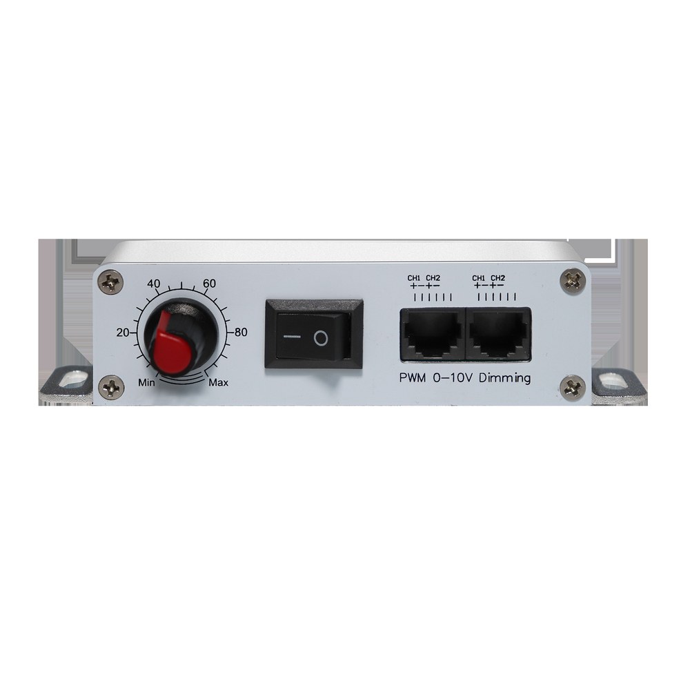
A representative controller makes the wiring concrete: a two-channel unit with a manual dial and separate PWM and 0-10V outputs can drive two independent zones, each with its own dim level, from one box on the wall.
What to check before specifying a dimmed circuit
- Does 50 percent signal give 50 percent light? Many drivers follow a curve shaped for human perception rather than a straight line, which is pleasant in an office and awkward in a grow room where you are trying to reproduce a PPFD setpoint. Ask for the dimming curve, or measure it.
- What happens at the bottom? Find out whether 0 V means off, 10 percent, or "the driver's minimum", and whether the fixture restarts cleanly from that state.
- How many drivers per controller output? Sink current, not fixture count, is the real limit on an analog line.
- Inrush when the contactor closes. A room full of drivers switched at once draws a surge; size breakers and contactors for it, not for the steady-state wattage.
- Override and fail state. Decide deliberately whether a lost control signal should mean full output, last level, or off.
How to verify the installation on site
Dimming is a claim until it is measured. Hold a quantum sensor at a fixed height under one fixture and record PPFD at 100, 75, 50 and 25 percent, then plot it. A near-straight line means the driver is behaving; a curve that sags at the bottom tells you the useful range starts higher than the dial suggests. For flicker, a slow-motion phone video of a moving object under the light will show banding if the modulation is deep, and a dedicated flicker meter gives a number rather than an impression.
Frequently asked questions
Can any LED grow light be dimmed?
Only fixtures whose driver was built for dimming. A constant-current driver without a control input cannot be dimmed from the outside, and adding a mains dimmer in front of it usually produces unstable output rather than smooth control.
Is 0-10V dimming the same as 1-10V dimming?
No. Both use a low-voltage DC signal, but the scale differs: on a 0-10V system 0 V means off or the lowest level, while a 1-10V system reserves the bottom of the range and treats 1 V as the minimum. Mixing the two on one controller produces dead travel or a fixture that never reaches full output.
Does dimming change the light spectrum?
With PWM or constant-current amplitude dimming the spectral distribution stays essentially the same, because the LEDs run at the same current and simply spend less time on, or run at proportionally lower current. Phase-cut dimming is the exception: distorting the mains waveform can disturb the driver and shift colour.
Why does my fixture buzz or flicker at low dim levels?
Two common causes. A phase-cut dimmer below its minimum load chops the waveform unevenly, which makes the driver cycle audibly and the LEDs flicker. On an analog control line, a control voltage that sags near the bottom of the range can drop under the driver threshold and switch the output on and off.
About the publisher
XineLam is an LED lighting manufacturer with 17 years of experience and 300+ patents in China and internationally. The company builds horticultural fixtures and the control accessories that drive them, including wall-mounted dimming controllers for PWM and 0-10V interfaces. This article is written as general technical guidance; the correct dimming method for a specific room depends on the drivers actually installed, and the driver datasheet should always be the final reference.
References
- DALI Alliance. Introducing DALI — digital lighting control, IEC 62386. https://www.dali-alliance.org/dali/
- Canadian Centre for Occupational Health and Safety. Lighting Ergonomics — Light Flicker (fact sheet last revised 17 December 2024). https://www.ccohs.ca/oshanswers/ergonomics/lighting/CCOHS_lighting_flicker.pdf