How High Should You Hang a Grow Light? Distance, Overlap and Load
Mounting height is usually chosen by copying the previous installation, and it silently sets two things at once: the photon dose at the canopy and how evenly that dose is spread. The suspension hardware then has to carry whatever is hung. Here is the geometry, and the load check that most rooms skip.
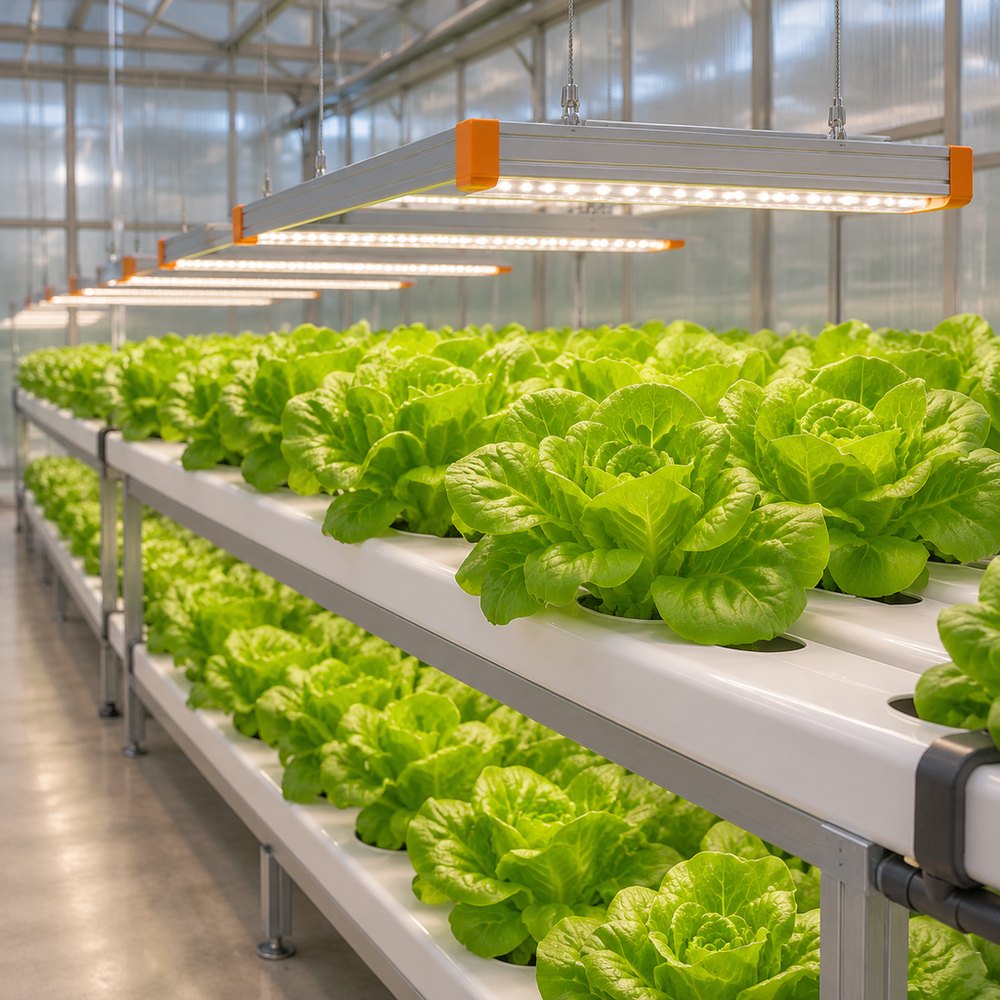
What mounting height actually controls
Three quantities move when a fixture goes up or down, and they move in different directions. Peak PPFD under the fixture falls as height increases. The illuminated footprint widens. And the overlap between neighbouring fixtures increases, which is the part that decides uniformity.
Only the first of those is intuitive, and it is the one people optimise for. Raising a bar by 10 cm reduces the photon flux density at the canopy, but it also spreads the beam so that the space between two bars fills in. In a room with wide spacing, the second effect dominates and the plants at the mid-point between bars gain more than the plants directly underneath lose.
The falloff curve is worth knowing before extrapolating measurements. A compact fixture behaves approximately like a point source in the far field, where intensity drops with the square of distance; the inverse square relationship is standard physics and appears in every introductory treatment [2]. A 1.2 m linear bar is closer to a line source, so in the near field its illuminance falls roughly linearly with distance, and reflector optics bend the curve further. Practical consequence: a change from 30 cm to 40 cm does not cost the same percentage as a change from 60 cm to 80 cm, so measure at the new height instead of scaling the old number.
The geometry: overlap ratio
For a fixture with a beam half-angle of theta mounted at height h above the canopy, the illuminated width on the canopy is approximately two times h times the tangent of theta. Divide that width by the centre-to-centre spacing between fixtures and you have the overlap ratio.
Worked example: a 120 degree beam has a half-angle of 60 degrees, and the tangent of 60 degrees is 1.73. At 0.40 m above the canopy the illuminated width is 2 x 0.40 x 1.73, or 1.39 m. If bars are spaced 0.80 m apart, the overlap ratio is 1.39 divided by 0.80, or 1.73. That is comfortable. At 0.25 m height the width falls to 0.87 m and the overlap ratio to 1.08, which is where visible striping starts to appear between rows.
As a working rule, an overlap ratio of at least 1.5 keeps the variation across a bay within roughly plus or minus 10 percent for typical bar optics; below about 1.2 the pattern between rows becomes visible to the eye and measurable with a sensor. These figures are geometric starting points, not guarantees, because reflector design redistributes light within the beam.
| Crop stage | Target PPFD at canopy (umol/m2/s) | Height above canopy | Bar spacing | Overlap ratio to aim for |
|---|---|---|---|---|
| Propagation, seedlings, cuttings | 100 to 200 | 0.25 to 0.50 m | 0.30 to 0.50 m | 1.5 or more |
| Leafy greens, lettuce | 200 to 400 | 0.30 to 0.60 m | 0.40 to 0.80 m | 1.5 or more |
| Herbs and microgreens | 150 to 300 | 0.20 to 0.40 m | 0.25 to 0.45 m | 1.6 or more |
| Fruiting crops, top lighting | 600 to 1000 | 0.60 to 1.20 m | 1.00 to 1.50 m | 1.4 or more |
Two corrections apply to every row. First, a fixture mounted at a fixed height above a growing canopy loses dose as the crop grows toward it, so either the schedule allows for re-hanging or the height is set for the final canopy. Second, wall reflectance changes the result: a white poly ceiling returns a meaningful share of the light, a black floor absorbs it, so the same layout in two rooms can differ by 10 to 20 percent in average PPFD. Michigan State University Extension makes the same point about interpreting intensity figures: what matters is the light at the plant, not the rating on the label [1].
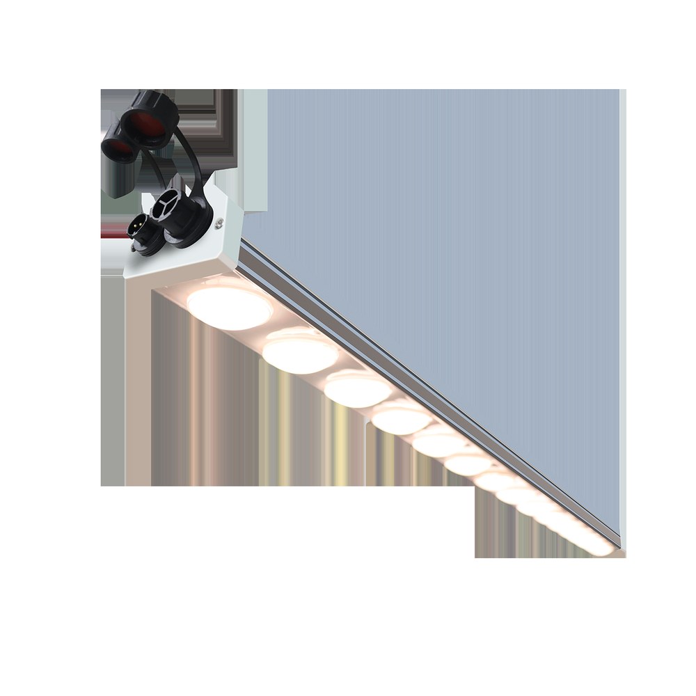
The load check most rooms skip
A grow room is a suspended load above people, plants and electrical equipment, yet the installation is often specified as "hang it from the purlin". The structural question is not the total weight of the fixtures divided by the floor area. It is the concentrated load at each attachment point, and whether the member carrying it was designed for that point load in addition to snow, wind and glazing.
Do the arithmetic per node. Add the fixture mass, the cable and clip mass, and any driver mounted on the fixture; then multiply by a safety factor that suits the site, with 2 as a common minimum for static suspended equipment and more where vibration, ice or seismic action is possible. Compare the result with the allowable point load the structure supplier states for that member, not with its total capacity.
| Item | What to obtain | Why it decides the layout |
|---|---|---|
| Fixture mass | Net weight per fixture, including driver and bracket | Sets the load per attachment point |
| Number of support points | Two per bar for anything over about 1 m | Single-point hanging allows rotation and swing |
| Cable and hardware rating | Working load of cable, clamps, thimbles, carabiners | The weakest element sets the chain's safe load |
| Structure allowable load | Point load permitted at the specific member and node | Total bay capacity is not the same as node capacity |
| Electrical provisions | Connector IP rating, strain relief, cable route | Wet rooms and washdown areas need sealed joints |
| Service clearance | Space for cleaning, inspection and re-lamping | Fixtures installed too close to structure cannot be serviced |
Details that decide whether the install survives
- Keep bars level. A tilted bar throws its beam sideways; the PPFD map shifts by more than most people expect, and the plants at one end of the row lose dose.
- Use two suspension points and a secondary retention. A fixture on a single central clip can rotate in service; a secondary wire independent of the primary suspension limits the consequences of a hardware failure.
- Leave thermal clearance above the fixture. A bar with 5 cm of air above it and a bar with 30 cm do not run at the same junction temperature, and photon output falls as junction temperature rises.
- Protect the cable at the connector. Support the cable so its weight is not carried by the plug, and keep connectors out of standing water in washdown rooms.
- Record the as-built heights. Write the measured height above the channel, not above the floor, on the room drawing; the next crop plan depends on it.
A six-step installation sequence
- Set the target PPFD and the allowed variation across the bay, for example 300 umol/m2/s plus or minus 10 percent.
- Choose spacing from the overlap rule, then choose height so the predicted dose meets the target at the final canopy.
- Confirm the allowable point load at each node with the structure supplier, and add a support rail if the answer is not documented.
- Hang, level and torque the hardware, with secondary retention on every fixture above a walkway.
- Measure PPFD on a grid at canopy height, at least nine points per bay, and adjust height or spacing where the map is uneven.
- Record heights, spacing, and the measured map, and re-measure after the first crop reaches the fixture.
Frequently asked questions
Is a lower mounting height always better because PPFD is higher?
No. Lowering a fixture raises the peak PPFD under it but also narrows the illuminated footprint, so the gap between the brightest and darkest plants grows. Uniformity depends on the overlap between neighbouring fixtures, which shrinks as height drops. Most rooms are better served by a moderate height with adequate overlap than by the lowest possible position.
Can I hang grow lights directly from the greenhouse purlin?
Only after the structure supplier confirms the allowable point load at that node. A purlin sized for glazing and snow may have very little margin for a row of fixtures plus cables, and the load is concentrated at discrete points rather than spread over the bay. When the allowable load is not documented, add a dedicated support rail spanning several frames instead of loading single purlins.
How does PPFD fall off with distance for a bar fixture?
For a point source in the far field, intensity falls with the square of distance. A long linear bar behaves more like a line source, so illuminance falls closer to linearly with distance in the near field, and the exact curve depends on the optics. That is why a distance change that seems small can move PPFD by 15 to 25 percent, and why the number should be measured at the new height rather than extrapolated.
Do the fixtures need a secondary safety retention?
It is good practice wherever fixtures hang above people or walkways. A secondary wire or lanyard independent of the primary suspension keeps a fixture from falling if a clip, thimble or cable clamp fails. Check the local electrical and workplace safety requirements for the site, and have the installation reviewed by the responsible engineer.
About the publisher
XineLam is an LED lighting manufacturer with 17 years of experience and 300+ patents in China and internationally. The company supplies horticultural luminaires for greenhouses, vertical farms and plant research rooms, and publishes technical notes on light measurement, thermal behaviour and installation practice. The fixture class named in this article is given as an application example; structural and electrical work should be reviewed by the responsible engineer for the site.
References: [1] Putting light intensity into perspective, Michigan State University Extension. [2] Inverse Square Law, HyperPhysics, Georgia State University.