Why Is Your LED Grow Light Running Hotter Than Before? Heat Sink Dust and Thermal Drift
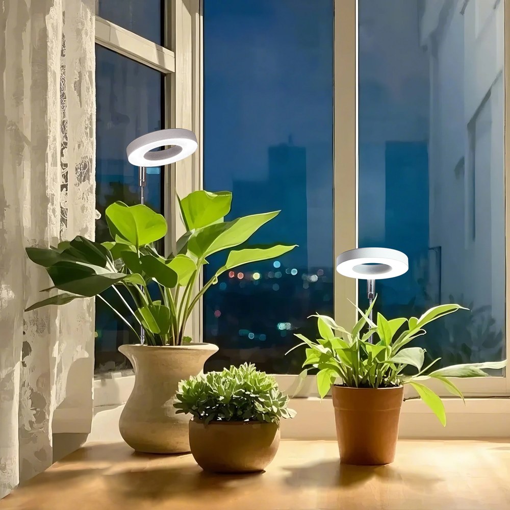
Growers tend to notice heat with the back of the hand. A fixture that was warm in its first season starts to feel hot in its third, output on the meter has slipped a few percent, and the first assumption is that the LEDs are simply ageing. Often they are not the cause. The more common story is that the path carrying heat away from the diode has become less effective, and the fixture is doing the same electrical work at a higher junction temperature.
This note sets out how heat actually leaves an LED luminaire, what a dust film does to that path, and how to tell thermal drift apart from ordinary lumen depreciation with measurements you can take in the room. It applies to bar fixtures, panels and ring lamps alike, because the physics does not change with the form factor.
Where the heat goes in an LED fixture
An LED converts only part of its input power into light. In a thermal analysis of a 9 W high-power LED array, Hou, Yang and Zhang put the split at 15–20 percent radiated as light and 80–85 percent dissipated as heat, and they note that the junction temperature must stay below 120 °C for the package to keep both its output and its life (Journal of Semiconductors, 2011). That ratio is the reason a 320 W horticultural bar can put more than 250 W of heat into a room, and it is the reason heat sink geometry matters more than most buyers expect.
The steady-state junction temperature is set by a chain of thermal resistances and by the air around the fixture:
Tj = Ta + Pheat × (Rj-c + Rc-h + Rh-a)
where Ta is ambient air temperature, Pheat is the electrical power that becomes heat, and the three resistances describe the die-to-case, case-to-heat-sink and heat-sink-to-air paths. Worked through for a 320 W fixture at 80 percent heat and a combined resistance of 0.35 °C/W, the junction sits about 90 °C above ambient: fine at 25 °C, marginal at 30 °C, and over the 120 °C limit at 35 °C. This is why two identical fixtures in two rooms age at different rates.
The same paper shows how much of that budget the heat sink itself controls. Under one set of conditions (9 W array, 25 °C ambient) three fin geometries produced very different junction temperatures:
| Heat sink geometry | Junction temperature | Headroom to the 120 °C limit |
|---|---|---|
| Plate fin | 68.20 °C | 51.8 °C |
| In-line pin fin | 70.66 °C | 49.3 °C |
| Staggered pin fin | 48.98 °C | 71.0 °C |
A staggered pin fin array ran almost 22 °C cooler than a plate fin sink of the same envelope. Design choices of that size are invisible in a product photo and decisive in year three, because every degree of junction temperature is spent from a life budget rather than a brightness budget.
What a dust film does to a heat sink
Fins work by presenting surface area to moving air. A settled film of dust does two things at once: it insulates the metal from the air, and it blocks the gaps between fins so that the boundary layer thickens and natural convection stalls. Neither effect shows up in a lumen meter immediately. What shows up first is a higher fin temperature at unchanged power.
Direct measurements of dust on LED heat sinks are scarce, but soiling on photovoltaic glass is measured well and the mechanism is the same optical and thermal fouling. In a six-week exposure study in two Pakistani climates, Rashid and co-authors measured a dust density of 6.388 g/m² reducing module efficiency by 15.08 percent, and 10.254 g/m² cutting output power by 25.42 percent; they also recorded that the dusty modules ran hotter than clean ones at equal irradiance (Heliyon, 2023). The numbers describe glass, not aluminium, and should not be transferred directly to a luminaire. What transfers is the direction and the timescale: six weeks of exposure, not six years, was enough for a settled film to change both transmission and temperature.
Five symptoms that separate thermal drift from lumen depreciation
Lumen depreciation is gradual, monotonic and independent of how the fixture is mounted. Thermal drift is local and conditional. These signs point at the thermal path:
- The fixture is hotter than its twin in the same room at the same dim level. Compare with an infrared thermometer at the same point on the sink, not by hand.
- Output recovers after cleaning. A 5–10 percent recovery on a quantum sensor after a clean is strong evidence that fouling, not the diode, was responsible.
- The hottest fixtures are the ones nearest the floor or the misting line, where splash and settled dust concentrate.
- Driver case temperature climbs while the driver current stays fixed, which usually means the driver is sitting in the fixture's own exhaust rather than in fresh air.
- Colour shift or flicker appears only after an hour of running, the classic signature of a junction that is being pushed past its comfort zone rather than a driver that is failing outright.
A cleaning interval that matches the room
There is no universal number, because dust load is a property of the room. The intervals below are starting points to be adjusted with the baseline measurement described in the next section.
| Room type | Dominant fouling source | Inspect every | Method |
|---|---|---|---|
| Sealed room, filtered intake, no open media | Lint, filter bypass | 6–12 months | Dry microfibre on fins, vacuum at low power |
| Greenhouse, soil or coco beds | Perlite, coir fines, pollen | 4–8 weeks in season | Soft brush, compressed air held at 30 cm |
| Aeroponic or misting room | Dried nutrient salt, condensation | 4–6 weeks | Damp cloth, then dry; inspect gaskets |
| Propagation room with high humidity | Salt film plus condensation | 6–8 weeks | Damp cloth on optics only, never on connectors |
Two rules keep cleaning from becoming the failure. Power down at the breaker and let the fixture reach room temperature first, because cold solvent on a hot lens crazes polycarbonate. And never direct compressed air into a driver enclosure or a connector body: you are as likely to drive dust inward as to blow it off.
How to measure thermal drift without a thermal chamber
You need an infrared thermometer with a known emissivity setting, or a contact probe on a painted surface, plus a record made on day one. Measure the room air temperature 1 m from the fixture, then the hottest readable point on the sink, and record the difference. Do it at full power, after 45 minutes of stable operation, with the same shield or reflector in place.
That single number, the sink rise above ambient, is your baseline. Re-measure at the start of each season. A rise of 8–12 °C above baseline at unchanged power and unchanged room temperature is the practical threshold for opening the fixture, cleaning the fins and re-checking the thermal interface. If the rise continues after a clean, the interface material or the fan bearings have degraded, and that is a service job rather than a maintenance job.
When cleaning is not enough
Three failures survive a clean. Thermal interface material dries and pumps out over thousands of thermal cycles, leaving an air gap between board and sink; the fix is replacement, not more paste. Sleeve-bearing fans lose speed silently, and a fan running at 60 percent of rated flow can halve the effective Rh-a. And electrolytic capacitors in the driver age faster at elevated case temperature, so a fixture that has been running hot for two seasons may need its driver replaced even though the LEDs are healthy.
This is also where specification decisions pay off. A die-cast body with a generous finned sink, a driver mounted outside the heat plume, and an enclosure rated for the room's actual dust and splash level will tolerate a missed cleaning cycle. A slim decorative body with the driver potted against the board will not. When selecting fixtures for a room with visible dust, ask for the measured case temperature at rated power in a stated ambient, not a lifetime headline: the United States Department of Energy's guidance on white LED lifetime makes the same point, that quoted life depends on the conditions under which lumen depreciation was measured (DOE Better Buildings, Lifetime of White LEDs). Where dimming is part of the control strategy, a 0–10 V controller such as our DM25 series lets a room run at 70–80 percent during warm weeks, which removes heat in proportion to the power saved while a maintenance slot is arranged.
About the publisher
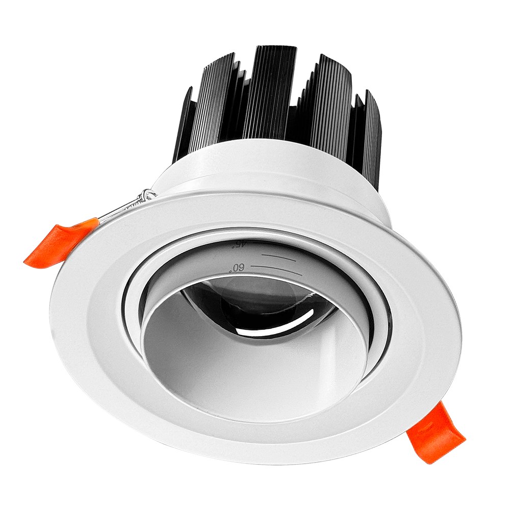
XineLam is a LED lighting manufacturer with 17 years of experience and 300+ patents in China and internationally. We design and produce horticultural luminaires and architectural LED fixtures, including the C100 downlight family shown above, with an emphasis on measured thermal performance rather than headline wattage.
Frequently asked questions
How do I know if my grow light is overheating or just running warm?
Compare the heat sink temperature rise above room temperature with the value you recorded when the fixture was new. A rise of 8 to 12 degrees Celsius above that baseline, measured at the same power and the same ambient, points to added thermal resistance rather than a hotter room.
Can dust on a heat sink really cost light output?
It costs headroom first and output second. A dust layer insulates the fins, the junction runs hotter, and LED output falls as junction temperature rises. Soiling studies on photovoltaic glass measured losses of 15 to 25 percent after six weeks of exposure, which shows how quickly a settled film changes an optical surface.
How often should LED grow lights be cleaned?
In a filtered, sealed room, every six to twelve months is usually enough. In a greenhouse or a room with perlite dust, open reservoirs or unfiltered intake air, inspect every four to eight weeks during the season and clean when a visible film forms on the fins.
Does dimming a fixture reduce its junction temperature?
Yes, roughly in proportion to the electrical power removed, because heat load follows drive current. Dimming to 80 percent removes about a fifth of the heat and the junction temperature falls by a similar share of the temperature rise, which is why dimming is a legitimate short-term fix while a fixture is waiting to be cleaned.
References
- Hou F, Yang D, Zhang G. Thermal analysis of LED lighting system with different fin heat sinks. Journal of Semiconductors 32(1):014006, 2011. https://www.jos.ac.cn/fileBDTXB/oldPDF/10092008.pdf
- Rashid M, Yousif M, Rashid Z, et al. Effect of dust accumulation on the performance of photovoltaic modules for different climate regions. Heliyon 9(12):e23069, 2023. https://pmc.ncbi.nlm.nih.gov/articles/PMC10731227/
- U.S. Department of Energy, Better Buildings Solution Center. Lifetime of White LEDs. https://betterbuildingssolutioncenter.energy.gov/resources/lifetime-white-leds