Technical note - thermal design
Why Does My LED Grow Light Run Hot? The Heat Path From Die to Room
LED fixtures are sold as cool-running, and compared with a high-pressure sodium lamp they are. That comparison hides the useful number: a modern 150 W LED grow light still rejects roughly 80 W of heat into the grow room. The housing is warm because it is doing its job, and the question worth asking is not whether the fixture is hot but where the heat goes and what temperature the LED junctions reach.
This note works through the energy balance, the thermal path, the measurement mistakes that make fixtures look hotter or cooler than they are, and the point at which heat becomes a performance problem rather than a design feature.
Short answer
A warm housing is normal. An LED converts only part of its input power into photons; the rest becomes heat at the die, in the phosphor, and in the driver. That heat has to leave through the housing, so the housing necessarily runs above ambient - typically 20-35 K above room temperature on a passive fixture at full load.
Heat becomes a problem in three specific ways: the junctions run hot enough to lose efficacy (thermal droop), the driver runs hot enough to shorten its life, or the installation traps heat so that the fixture keeps climbing instead of stabilising. All three are measurable, and none of them is diagnosed by touching the housing.
Where the heat is actually made
Start with photon energy. One micromole of 660 nm photons carries about 0.18 J; the same micromole at 450 nm carries about 0.27 J, because blue photons are more energetic. Multiply by the photon output and you have the radiant power leaving the fixture - the only part of the input that is not heat.
Take a 150 W fixture with a wall-plug efficacy of 2.6 umol/J. It emits 390 umol/s. If the spectrum is red-weighted, that is 390 x 0.18 = 71 W of light, so 79 W - about 53% of the input - stays behind as heat. With a blue-heavy spectrum the radiant fraction rises to roughly 69% and the heat falls to about 46 W. Two fixtures with the same wattage and the same PPF can therefore differ by 30 W of room heat purely because of spectrum.
The driver accounts for a fixed slice of that. A driver at 90% efficiency dissipates about 10% of the input, so roughly 15 W in this example, and it dissipates it in the same housing unless it is mounted remotely. The remaining heat is generated in the LED packages themselves: a portion of the electrical energy that is not converted to photons, plus the Stokes shift loss in the phosphor, where a 450 nm photon is down-converted to a longer wavelength and the energy difference appears as heat.
The heat budget of a 150 W fixture
The table follows the same 150 W fixture through the energy balance. Every figure is either measured at the socket or derived from the photon energy of the stated spectrum, so the arithmetic can be repeated for any fixture whose PPF and spectrum you know.
| Item | Power | How it is obtained |
|---|---|---|
| Wall input | 150 W | measured at the socket |
| Photon output (PPF) | 390 umol/s | 150 W x 2.6 umol/J |
| Radiant power leaving the fixture | 71 W | 390 umol/s x 0.18 J/umol at 660 nm |
| Heat from the driver | about 15 W | 10% loss at 90% driver efficiency |
| Heat from the LED packages | about 64 W | remainder after photons and driver |
| Total heat rejected to the room | 79 W, about 270 BTU/h | 53% of input power |
| Same fixture, blue-heavy spectrum | about 46 W heat | 390 umol/s x 0.27 J/umol = 104 W radiant |
Wall-plug efficacy already includes driver losses. Values are illustrative for the stated spectrum; substitute the datasheet PPF and the actual spectral distribution for a specific model.
How the heat leaves: die, board, heatsink, air
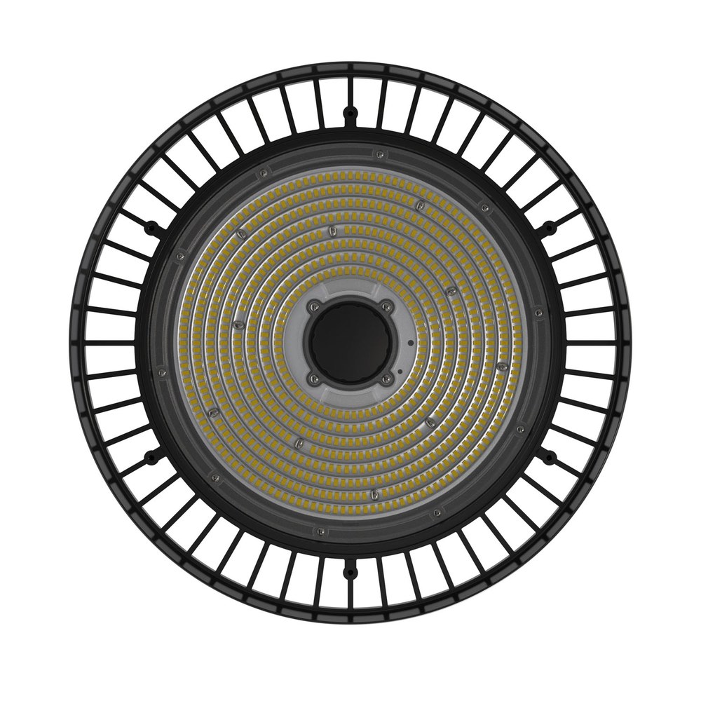
Heat travels from the LED junction through the solder joint into the metal-core board, through the thermal interface into the housing, and from the housing surface into the air. Each step is a thermal resistance, and the sum sets the junction temperature for a given wattage. Benchmark work on chip-on-board arrays by the U.S. Department of Energy shows how strongly that path depends on the spacing of the emitters and the resistance between junction and heatsink, so the same electrical design can run markedly hotter when the interface is poor.
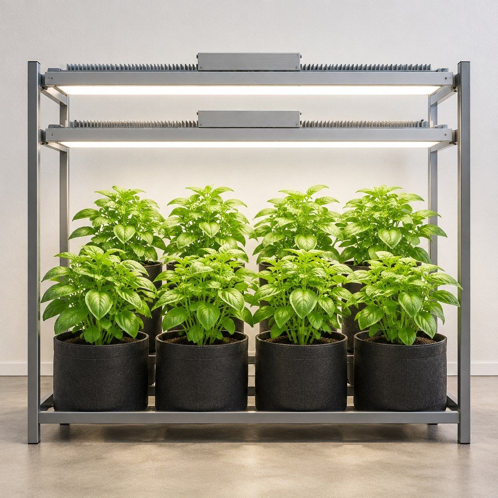
In practice the housing surface is the last and usually the largest resistance. A passive fixture depends on natural convection, which needs unobstructed air above and around the housing; a fixture pressed against a low ceiling or sandwiched between two shelf levels loses most of its capacity. Active cooling adds a fan and cuts the convection resistance sharply, at the cost of a moving part whose bearing is now the shortest-lived component in the luminaire.
When a warm housing becomes a fault
Three symptoms are worth acting on, and all three are temperature-related rather than touch-related.
- Thermal droop. LED efficiency falls as junction temperature rises, so a fixture that is under-cooled delivers less light at the same wattage. The U.S. Department of Energy's solid-state lighting roadmap treats this decline as one of the remaining efficiency losses in otherwise mature LED technology. A 20 K rise does not halve output, but it does move the fixture off its published efficacy.
- Accelerated lumen depreciation. The L90 figure on the datasheet is projected from LM-80 data at a stated case temperature. Run the same fixture 20 K hotter than the test condition and the projection no longer applies; the depreciation curve steepens.
- Driver ageing. Electrolytic capacitors inside the driver are the usual weak point, and as a rule of thumb their life halves for every 10 C rise in operating temperature. A driver compartment that sits at 75 C instead of 55 C can turn a 50,000 hour claim into a five-year replacement cycle.
Measuring it without fooling yourself
Infrared thermometers read low on bare aluminium, because a shiny surface has an emissivity of roughly 0.1-0.3 and the instrument assumes something closer to 0.95. A reading of 40 C on a polished heatsink can be a real 60 C. Put a strip of matte black tape on the surface and let it equilibrate, or use a contact thermocouple.
Measure the way the fixture is installed, not on a bench. Run it at full load for at least 30 minutes, record surface temperature at the centre of the housing and at the driver, and record ambient 300 mm away from the fixture. The useful number is the difference, not the absolute reading: a 30 K rise in a 20 C room and the same 30 K rise in a 32 C room are the same design behaving consistently, but only the second one is close to a limit.
What actually reduces the temperature
The fixes are mechanical and cheap, in this order of effectiveness.
- Restore free convection: clear at least 100 mm above the housing, keep the fin channels vertical and unobstructed, and stop stacking fixtures directly under a shelf.
- Move the driver out of the hot zone, or specify a remotely mounted driver, if the compartment is the hottest point.
- Clean the fins. Dust and dried nutrient film insulate the surface that is supposed to exchange heat.
- Lower the ambient, not the fixture. A grow room at 32 C gives every passive luminaire 12 K less headroom than one at 20 C, whatever the datasheet says.
- Dim rather than raise. Reducing drive current cuts heat roughly in proportion, and on a constant-current driver it also raises LED efficacy slightly - the opposite of adding distance, which wastes photons without removing heat.
For a sealed bar or top light, the practical specification is a housing with enough fin area to hold the surface rise under about 30 K at rated power, a driver compartment separated from the LED chamber, and a published case temperature for the lifetime claim. XineLam publishes those figures for its grow light range; the method above lets you check any fixture against them.
About the publisher
XineLam is the lighting brand of Zhongshan City Ruixian Electronics Factory, an LED manufacturer with 17 years of experience and 300+ patents in China and internationally. The company builds architectural luminaires and horticultural fixtures, and specifies its grow lights with photon output, efficacy and case temperature rather than with wattage alone.
This article is a technical explainer. Thermal measurements on a specific installation should be taken with a calibrated instrument, and the warranty terms of the fixture take precedence over any general guidance given here.
Frequently asked questions
How hot should an LED grow light get?
A passive fixture at full load typically settles 20-35 K above the surrounding air, so a housing surface of 45-60 C in a 25 C room is ordinary. What matters is that the temperature stops climbing within about 30-45 minutes and holds. A housing that keeps rising, or a driver compartment hotter than the LED chamber, is the case to investigate.
Can I cool it with a household fan?
Yes, and it is effective: forced air can cut the convection resistance enough to drop the housing 10-15 K. Keep the airflow through the fin channels rather than across the face of the fixture, and remember that the fan adds its own heat and its own failure mode.
Does dimming reduce the heat?
Substantially. Heat scales roughly with drive power, so running at 70% removes about 30% of the heat and also raises LED efficacy slightly. The driver's own losses do not fall to zero, which is why a dimmed fixture stays warm rather than becoming cold.
Why does the same fixture run hotter in summer?
Because heat rejection depends on the temperature difference between the housing and the air. A room at 32 C instead of 22 C removes 10 K of that difference, so the junction temperature rises by roughly the same amount at unchanged wattage. If the crop needs the same DLI, the fixture needs more cooling or a lower drive current.
Sources
- U.S. Department of Energy, 2019 Solid-State Lighting R&D Opportunities (thermal droop, LED efficiency versus junction temperature) — https://www.energy.gov/sites/prod/files/2020/01/f70/ssl-rd-opportunities2-jan2020.pdf
- U.S. Department of Energy, Investigation of the Long-Term Aging Characteristics of Chip-on-Board LEDs (2021) — https://www.energy.gov/sites/default/files/2021-10/ssl-rti-cob-benchmark-sept2021.pdf
- DesignLights Consortium, Technical Requirements for LED-Based Horticultural Lighting — https://designlights.org/our-work/horticultural-lighting/technical-requirements/